Maintenance for the Remote Fire Gas Gun
Also available as a printer-friendly PDF
.gif)
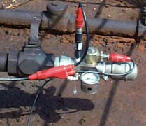
Remote Fire Gas Gun Assembly Drawing
View larger drawing: Full size
(285k 2500 x 1100), Full size vertical orientation (294k 1100x2500),
Medium
(50k 800 x 352), Left side (90k 1164x1100) or Right side
(190k 1376 x 1100)
- When the remote fire gas gun is placed onto the well, charge the gas
gun volume chamber to a pressure in excess of well pressure before
opening the casing valve. The remote fire gas gun utilizes a solenoid
with a small dart valve and a small orifice. The dart valve releases
gas from behind a 1/2 inch moveable piston that allows gas from the gas
gun volume chamber to flow into the well. These small moving parts
will become clogged and inoperable if sand and debris are blown from
the well into the gas gun volume chamber. Debris and sand will prevent
the dart valve from properly sealing, and gas will bleed continuously
from the gas gun volume chamber into the well. This requires that the
gas gun be disassembled, cleaned and reassembled. The gas gun volume
chamber should be charged to a pressure in excess of well pressure
with CO2 or nitrogen gas to close the gas valve and prevent well
gasses and debris from the well being blown into the gas gun volume
chamber. When the remote fire gas gun is placed onto the well, charge
the gas gun volume chamber to a pressure in excess of well pressure
before opening the casing valve. This will close the gas valve and
prevent debris from being blown into the gas gun mechanism. Also, most
well gases contain water vapor. This water vapor will be blown into
the gas gun volume chamber if the gas valve is not closed by pressure
in the volume chamber in excess of the well pressure. This water will
cause corrosion and rust that will further contaminate the mechanism
- Protect the remote fire gas gun housing threads from corrosion. The
threads on the gas gun can become damaged or corroded. Protect the threads
with a light coating of grease or oil and place a plastic cap on the
threads. The pressure rating of 2000 psi should be reduced if corrosion or
worn threads exists. A corrosion protective coated steel 2" 11 1/2 V
male to female adapter (mic protector) is available for protecting the gas
gun threads and microphone. The mic protector is supplied with new remote
fire gas guns. The mic protector should be installed and replaced as
needed.
- Clean the dart valve, if gas is constantly leaking from the hole
underneath the pressure gage. If pressure is constantly leaking out the
small pressure relief hole underneath the pressure gage, then probably the
dart valve inside the solenoid assembly is not sealing, allowing pressure
to leak out the pressure relief hole. The solution is to disassemble the
solenoid and clean the dart valve assembly. Use the spanner wrench to
remove the nut and use your hand to remove the solenoid coil housing.
Remove the flux washer that fits on the bottom of coil housing and again
use the spanner wrench to unscrew the plunger assembly from the housing.
When removing the plunger housing be careful to not drop the plunger
spring or dart valve and plunger. The dart valve is the little plastic
needle inside of the plunger. You should visually examine the dart valve
tip for any debris. Any debris can prevent the dart valve from making a
gas tight seal in the dart valve seat; just a grain of sand, a small metal
shaving, or other debris can get between the dart valve and seat and can
prevent an airtight seal. The debris will allow pressurized gas to leak
past the dart valve and out of the vent. To clean the dart valve wipe the
tip with a soft clean cloth or in the field your finger will normally work
ok. Once the dart valve is clean, then reassemble the solenoid assembly.
If the tip of the dart valve tip is damaged, then it must be replaced.
The dart valve can be removed from the plunger. Then replace the dart
valve with new valve and reassemble the solenoid assembly.
After cleaning the dart valve and if the remote fire gas gun still
leaks out the small pressure relief hole underneath the pressure gage,
then the dart valve seat should be inspected. The dart valve seat sits
just underneath the dart valve plunger assembly and is held in place with
an O-ring. The seat can be removed and there could be debris lodged inside
the seat. Spray contact cleaner through the dart valve hole and through
the two slots on either side of dart valve seat. The spray will purge out
all debris and clean the hole. The O-ring on the dart valve seat should be
free of cuts and abrasions. After the seat is inspected, then replace and
lubricate the O-ring on the dart valve seat. Then reassemble the solenoid
assembly and tighten with a wrench.
- Replace the O-ring on the gas valve, if gas is leaks from the bottom
end of gun. The symptom of gas pressure bleeding past the gas valve and
leaking out the bottom end of gun, leaking into the well, is shown by the
pressure gauge not building or holding a positive pressure. Most likely
the problem is caused by the smaller of the two O-rings (WG-1700) on the
gas valve being cut. The cut in the O-ring is allowing gas pressure to
flow past the O-ring and into the well. The solution to repair this
problem is to remove the gas valve and replace the O-ring.
To disassemble
the remote fire gun:
- Remove the volume chamber to expose the orifice
and the orifice housing,
- Remove the orifice housing with a 7/8 inch
socket wrench
- Use the repair kit's 6-32 machine screw to screw in the
top of the gas valve, and
- Pull the gas valve from the housing.
Inspect
the small O-ring on the bottom side of the gas valve for cuts or misshapenness.
The smaller of the two O-rings does most of the work and most of the
sealing, because it fits in a hole in the bottom of the housing and seals
off the chamber. The gas valve is continuously working up and down as the
gun is fired, so the small O-ring takes a lot of wear and tear. When the
gas valve is removed, then O-ring lubricant or bearing grease should be
applied to the O-rings. The lubrication helps gas valve to slide more
freely and lengthens the life the O-rings. Inspect the WG-1600 O-ring on
the bottom side of the orifice housing and replace if the O-ring is cut or
if it is worn. Failure of the WG-1600 O-ring can prevent the orifice from
functioning properly, allowing gas pressure to bypass the orifice and leak
underneath the orifice housing into the gas valve chamber. This type of
leak prevents gas pressure from being bled off of the topside of the gas
valve rapidly enough for the gun to fire properly.
- Clean the orifice and orifice housing if they become clogged. The
orifice has a 0.015" hole through its center and it is screwed into
the orifice housing. The orifice or the orifice housing needs to be
cleaned if clogged with debris that restricts the flow of gas pressure
into the volume chamber. The orifice and orifice housing are cleaned by
first removing them from the gun, then spraying WD 40 or a pressurized
electrical contact cleaner through them. The orifice is removable and can
be replaced with a new one, however the orifice is normally reliable and
trouble free.
- Lubricate O-rings on the moving gas valve. Put a little bit of
lubricant inside the gun as well. Make sure the chamber inside the gun is
clean where the gas valve actually operates. A build-up of gunk or debris
inside the volume chamber can prevent that gas valve from moving freely
and the gas valve has to move freely to work properly. Do not wait for
long periods between maintenance of the gas valve. The remote fire gun
should be taken apart, cleaned and re-lubricate the O-rings. Lack of
proper maintenance will allow the O-rings to become dry and friction can
actually stick that gas valve inside the gun. The O-rings have enough
friction on them that if they become dry, then they can stick that gas
valve and not allow the remote fire gun to cock. If excessive pressure is
required to cock the remote fire gas gun, then the gas valve probably
needs to be lubricated. If a pressure build-up test is to be preformed on
a well, then the recommended practice is to inspect both the dart valve
and gas valve before the start of the test.
- Do not fill the gas gun with liquid CO2. Occasionally, the valve
core inside the filler connector housing can stick open and blow CO2 gas
out of the volume chamber into the atmosphere. The gas leakage is caused
by the CO2 freezing, as it is discharged into the gas gun volume chamber.
Filling the gun with gas instead of liquid CO2 can prevent freezing of the
valve core. When the 7.5 ounce CO2 bottle is used, the top of the bottle
should be above the bottom of the bottle so that gas at the top is
discharged from the bottle into the gun instead of liquid CO2 from the
bottom of the bottle. If the gas gun is filled with the 7.5 ounce bottle
located directly above the gas gun, the liquid CO2 in the 7.5 ounce bottle
can freeze as it enters the gas gun and cause the gas gun filler connector
to leak when the 7.5 ounce bottle is removed from the gun connector.
- Keep debris out of the filler connector housing. If debris in the
valve core filler connector housing causes the gas gun to leak, lubricate
the valve core with light oil. Remove the filler connector housing and add
light oil directly onto the valve core. Install the filler connector
housing and then refill and discharge the gas gun with CO2 a few times.
Firing the gun multiple times will remove the debris from the valve core.
Be sure that the valve core is properly tightened while the filler
connector housing is removed.
- Replace filler connector housing when small fill tube is damaged.
When the 7.5 ounce CO2 bottle is used to fill the remote fire gas gun,
occasionally, the 7.5 ounce CO2 bottle will be forced from the filler
connector housing due to the pressure in the CO2 bottle forcing the filler
connector's nozzle away from the filler connector housing. A worn or bent
or flattened small fill tube in the filler connector housing prevents the
CO2 gas from being released into the gas gun volume chamber. The solution
is to replace filler connector housing.
- The internal wire on the remote fire gas gun microphone BNC
connector can be broken. Pulling the microphone BNC connector too far from
the housing will break the internal wire. If the coax cable becomes stuck
to the microphone BNC connector do not try to jerk it loose. Be sure to
use a 90-degree "L" electrical BNC connector with the remote
fire gas gun to protect the BNC connector on the gas gun. When attaching
and removing a cable to the BNC connector or to the 90-degree
"L" electrical BNC connector, use care. These connections must
be maintained clean at all times.
- When switching the filler connector from an empty bottle to a full
bottle, remove the filler connector from the empty bottle and wait 5
minutes for the swollen O-ring to reduce in size. Generally, the filler
connector on a 7.5-ounce bottle is removed when the bottle is empty and
the filler connector is placed onto a full CO2 bottle in order to continue
testing wells. When the filler connector is removed, the purple O-ring on
the filler connector will swell. When the filler connector with the
swollen O- ring is placed onto a 7.5 ounce CO2 bottle, the swollen O-ring
is generally damaged when the filler connector is attached to the new
bottle that causes the CO2 to leak from the bottle. When switching the
filler connector from an empty 7.5 ounce CO2 bottle to a full 7.5 ounce
CO2 bottle, remove the filler connector from the empty bottle and wait 5
minutes for the swollen O-ring to reduce in size. After it reduces to
normal size, lubricate the O-ring with a few drops of oil and install onto
the full 7.5-ounce CO2 bottle.
- The microphone cannot be repaired in the field, do not disassemble.
If fluids enter the inside of the microphone, the microphone will be
damaged. Saltwater will cause immediate failure of the microphone if it is
allowed to enter the inside of the microphone. Clean the lower threaded
portion of the remote fire gas gun after each day's use with a mild
cleaner such as soapy water, alcohol, WD 40 or a pressurized electrical
contact cleaner which can be obtained from an electrical supply store.
Then, coat the inside of the gas gun lower chamber with grease or a light
coating of oil. If the microphone is removed from the remote fire gas gun,
be sure to clean the lower portion of the remote fire gas gun thoroughly
and also the microphone before attempting to reinstall the microphone into
the lower chamber. If the microphone is removed from the remote fire gas
gun always replace the O-ring with a new O-ring that fits over the
electrical connection between the microphone and the remote fire gas gun.
Be sure to lubricate the O-ring with an O-ring lubricant, grease or oil.
- When used on wells that are chemically treated at the surface, the Echometer gas
gun should be cleaned at the end of each day. The gun and microphone are
constructed from stainless steel and the microphone has Mylar plastic
coatings. Almost all hydrocarbon oils and water will not damage the
microphone. Some wells are chemically treated at the surface for
corrosion. High concentrations of some chemicals are corrosive and will
cause corrosion to the stainless steel Echometer gas gun parts. If the
wells to be acoustically tested are chemically treated at the surface, the
Echometer gas gun should be cleaned at the end of each day because the
chemical may be corrosive to gas gun parts. To clean the gas gun, first,
pressurize the gas gun. Then use a hydrocarbon solvent, soapy water,
alcohol or household cleaning agent to clean the portion of the gas gun
that is exposed to well gases. Allow parts to drip dry or blow dry with
compressed gas psi.
Repair Personnel:
Marvin Craft: Extension 20
Rusty Ham: Extension 19